Main Robot 3D Render
What is a Mecanum Drivetrain?
A Mecanum drivetrain is a four-wheeled drivetrain with special wheels. There are two different types of Mecanum wheels, a left and right wheel. They must be placed in certain places on the robot if you want to utilize the maneuverability of the Mecanum drive. Mecanum wheels have small rollers on them at a certain angle so it allows it to move more directions than forwards and backwards. Depending upon how fast all the wheels are spinning and the direction they are spinning, a full 360 degrees of motion can be achieved by the robot without changing its heading.
A Mecanum drivetrain is a four-wheeled drivetrain with special wheels. There are two different types of Mecanum wheels, a left and right wheel. They must be placed in certain places on the robot if you want to utilize the maneuverability of the Mecanum drive. Mecanum wheels have small rollers on them at a certain angle so it allows it to move more directions than forwards and backwards. Depending upon how fast all the wheels are spinning and the direction they are spinning, a full 360 degrees of motion can be achieved by the robot without changing its heading.


3D printed spacers for the wheel mount assembly
To add chain to the wheel, we needed to put sprockets on the wheel. When we put the sprocket on the wheel using PTC Creo, it was very close to the rollers. We solved this problem by designing a spacer for the sprocket. Next, we assembled was the sprocket on the motor. First, we assembled the sprocket flush to the wheel. We noticed that it was not aligned to the wheel’s sprocket, so we designed a spacer that fits in between the motor and the sprocket. One issue with this design is that the weight of the robot must pass through the 3D printed spacer to get to the wheels. We normally use polylactic acid (PLA) to 3D print, but the force of the weight the robot would be too great for the PLA. Instead, we are using a 15% carbon fiber/85% PLA
To add chain to the wheel, we needed to put sprockets on the wheel. When we put the sprocket on the wheel using PTC Creo, it was very close to the rollers. We solved this problem by designing a spacer for the sprocket. Next, we assembled was the sprocket on the motor. First, we assembled the sprocket flush to the wheel. We noticed that it was not aligned to the wheel’s sprocket, so we designed a spacer that fits in between the motor and the sprocket. One issue with this design is that the weight of the robot must pass through the 3D printed spacer to get to the wheels. We normally use polylactic acid (PLA) to 3D print, but the force of the weight the robot would be too great for the PLA. Instead, we are using a 15% carbon fiber/85% PLA
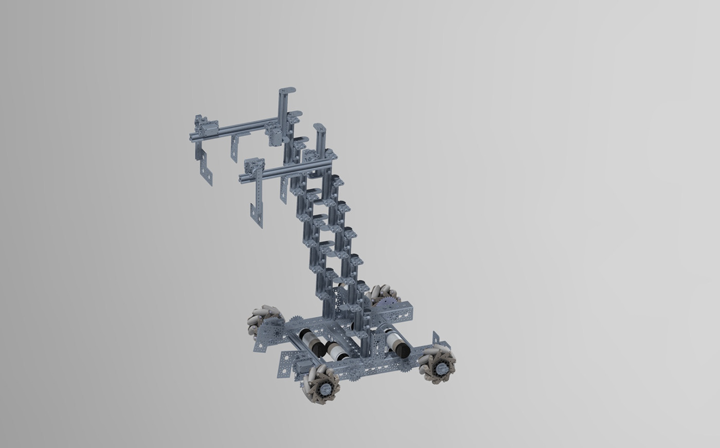
Lift Assembly
We switched to a Misumi-lift for our new lift. We used nine Misumi drawer-slides. We did this in order to maximize the space on our robot. We found that with our previous lift, it was taking up too much space. In between each slide, we are using a 3D printed spacer in order to brace the lift as it goes up. We used a carbon fiber spacer on the front because the first few Misumis experience the most tension and their brace needs to be the strongest. The reason we chose the cascading x-rail lift as our initial design was because our prototype showed that this had a very stable build and it was reliable. We found that this design was suitable for early stages and gave us a competitive lead going into the competition.


Stone Dumper Mechanism
Our new dumper can grip the stones, rotate to change the orientation of the stones, and extend to place the stones on the foundation. It is mounted to the top of the lift via Actobotics X-rails. Our dumper uses two 300MM Misumis to extend out of the robot and over the foundation. They give us a reach of 360 MM when fully extended. The dumper includes a total of 3 servos, 2 rev servos for the gripper and rotation, and one Hitec servo (HSR-H9383TH) for driving the outward extending Misumis. The HSR-H9383TH has the capability to make 4 rotations, which is ideal when powering slides because the extra freedom allows us to extend our dumper further.
Double Spooling:
In a vertical lift, the slides are brought down by gravity when you unspool the thread, but in horizonal slides, we lose the aid of gravity to close the lift. To solve this problem, we are double spooling the extension Misumis to allow us to both extend and retract the slides with the same servo. Double spooling involves having 2 spools that are both spooled in opposite directions. The threads are strung opposite form each other.


Intake Arm Designs
Pincher Design
One crucial part of our robot was our intake. Our first design was a pincher design where we wanted to create a claw like mechanism that could pick up the stones and deliver them to the build side. This design easily be able to stack stones on the build side. With a stationary plate in the back, the pincher would be able to naturally align itself to the stones. After careful consideration we decided to not go for this design. Our initial analysis lead us to think that it would be difficult for us to pick up the stones from the quarry side based on the design and also the slowness of the intake compared to other designs
One crucial part of our robot was our intake. Our first design was a pincher design where we wanted to create a claw like mechanism that could pick up the stones and deliver them to the build side. This design easily be able to stack stones on the build side. With a stationary plate in the back, the pincher would be able to naturally align itself to the stones. After careful consideration we decided to not go for this design. Our initial analysis lead us to think that it would be difficult for us to pick up the stones from the quarry side based on the design and also the slowness of the intake compared to other designs
Wheel Design
This design instantly allows us to intake the stones. It is simple and very effective needing very few parts to prototype. We needed a couple of motors attached to each of the wheel and a rubber wheel would be able to create enough friction to hold on to the stone.
This design instantly allows us to intake the stones. It is simple and very effective needing very few parts to prototype. We needed a couple of motors attached to each of the wheel and a rubber wheel would be able to create enough friction to hold on to the stone.


Intake Assembly
We decided to use a wheel intake so that our robot performance would be much more efficient. This would make intaking the stones much faster because the wheels would be brought in directly where it could be picked up by the stone. After a series of test, we found that sometimes the stone slipped out of the robot. This is why we added another wheel behind the main wheel to act like a guide. This wheel would push the stone all the way to the back so that it would be picked up in the same place every time.

FINAL ROBOT RENDER


